by Sarra Zoghlami
For mold designers who would like to use SimForm to identify the areas of their mold in most need of cooling.
Introduction
This article is a step-by-step guide to using SimForm to run a thermal analysis of your mold design without cooling channels, which lets you identify high temperature areas and critical components that need to be efficiently cooled. This allows you to make calculated decisions about the location of cooling channels and mechanisms in the mold.
Content
Model description
SimForm supports analysis for detailed mold designs that contains multiple components and mechanisms, as well as simple mold designs with the plastic part and a single box around it.
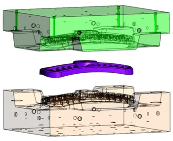
This example uses a model of an All-Terrain Vehicle (ATV) grill mold that contains a plastic part, core, and cavity.
Create a new project and job
In SimForm, you use a project to test different designs of the plastic part and mold for your application. A single test of the model is called a job. A project can contain multiple jobs with different variations of the part and mold to easily converge upon the optimal design.
Each job allows you to evaluate a specific cooling channel design, look at design parameters like how many cooling lines are needed, decide where baffles should be located, and determine the improvement that can be gained from conformal cooling, or inserts in a more conductive material.
For this example, you will create a new design project and a new job for the channel planner analysis.
- On the Projects page, click Design Project.
 The Add Design Project window opens.
When you create a new SimForm project, you redeem 10 credits from your credit balance. Each project lets you to simulate up to 10 different solves (5 solves during the free trial) without using more credits. - In the Add Design Project window, type a meaningful name that identifies your part design, for example ATV grill.
- Click ADD.
The Add a new job window opens. - In the Add a new job window, type the job name, for example Channel Planner.
- Click Select file, select the CAD files to upload your mold and plastic part designs, and click ADD.
Categorize the mold and plastic part components
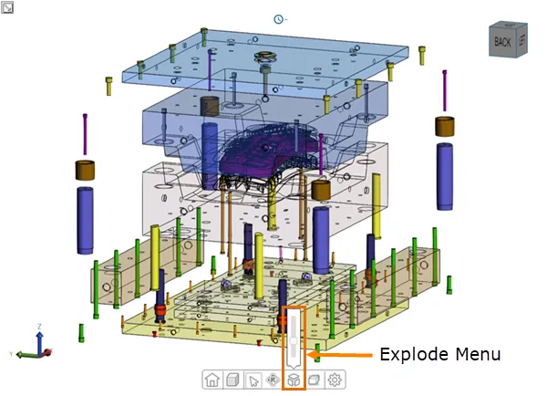
After uploading the CAD geometry, you must categorize the model components for SimForm to identify the mold components, plastic part, and channels.
For complex mold geometry models, you can use the slider of the Explode Menu to display all the mold components separately and use the Model Tree to hide the parts that you do not want to include in your analysis.
Mold group panels in SimForm allow you to categorize the different parts of your mold based on their material properties. If your model contains inserts with different materials than the mold, you can use one mold group panel to identify the inserts and another mold group panel to identify all other parts of the mold with the same metal material.
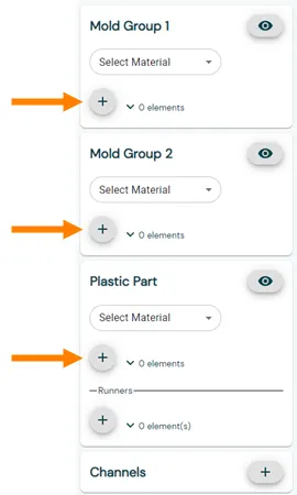
By default, the setup page contains one mold group. You can add additional mold groups to categorize and analyze various material properties within your mold design.
The mold design used in this example does not contain inserts made of different metal materials. Therefore, you can use the Mold Group 1 panel to categorize the core and add an additional mold group panel to categorize the cavity. This allows you to display the temperature of the core and cavity separately while looking at the results.
Follow this procedure to categorize the core, cavity, and the plastic part:
- Click Mold Group to create an additional mold group.

- Graphically select the mold core.
- In the Mold Group 1 panel, click the + sign to define the selected body as a core.

- Repeat steps 1 and 2 to define all the core components of your mold.
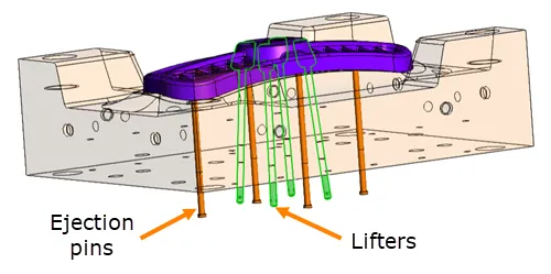
If your model contains ejection pins and lifters on the core side, categorize them as a part of the core. Since these components are in contact with the plastic part, not including them in the analysis creates an additional source of cooling that distorts the temperature results.
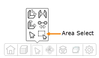
If your model contains multiple components of the same type, you can press Ctrl and select all the components one by one, or use Area Select to select them all.
- Click the visibility icon to hide the categorized components.
 This allows you to verify if all your components are correctly categorized by hiding the selected ones.
 - Repeat steps 1 to 4 to select and define the cavity in the Mold Group 2 panel and plastic part components in the Plastic Part panel.
- If your mold model contains cold runners, graphically select the runner components, and, in the Plastic Part panel, under the Runners sub-panel, click Add to define them. This allows SimForm to properly manage the runner when calculating the cooling time.
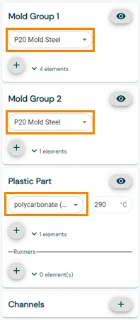
Select materials
After categorizing all the components, you must define the mold components, and plastic part materials. SimForm uses the thermal properties of these materials to compute the heat transfer between the mold and plastic part.
To define the mold, and plastic part materials, expand the Select Material list in the corresponding panel and select the desired materials or define new materials.
When you select the plastic part material, SimForm sets the injection temperature for the plastic based on manufacturer recommendations. You can modify the injection temperatures of the plastic part if necessary.
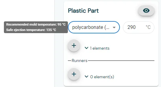
When you hover the mouse over the plastic part material, SimForm displays the recommended mold temperature and the safe ejection temperature of the plastic part.
Solve the model
After you prepared your model by categorizing the model components and defining materials and initial temperatures, the Submit Job button becomes available.
You can perform a solve by clicking Submit Job.

The job status changes from Not submitted to Submitted. The job status switches to In progress during the solve and to Completed at the end of the solve.
Analyze the results
When the job finishes, click Results to open the results page.

On the results page, you can:
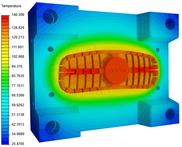
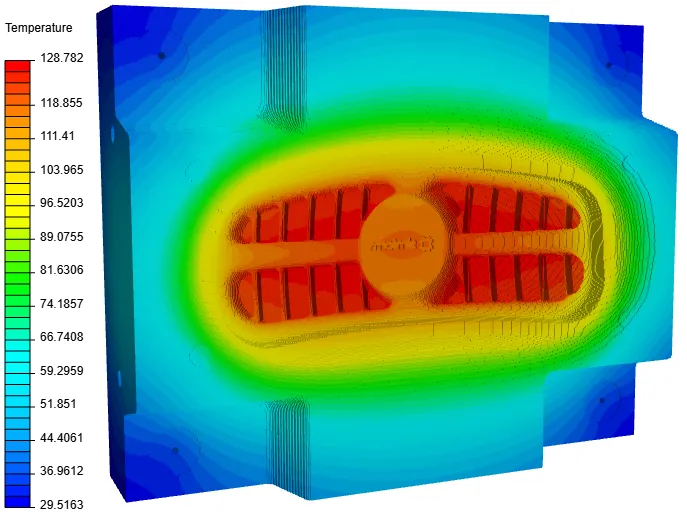
- Display temperature results on specific component types when you select the corresponding component check box. This allows you to identify high-temperature areas so you can decide the location of cooling channels and mechanisms like sliders in the mold. Clear the component check box to hide its results.
| Core temperature results | Cavity temperature results |
|---|---|
 |  |
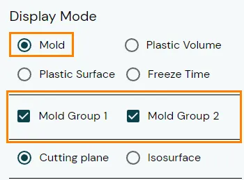
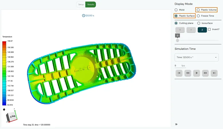
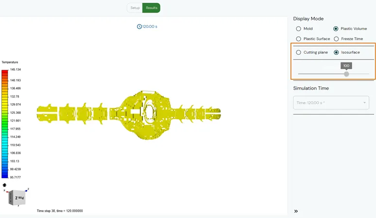
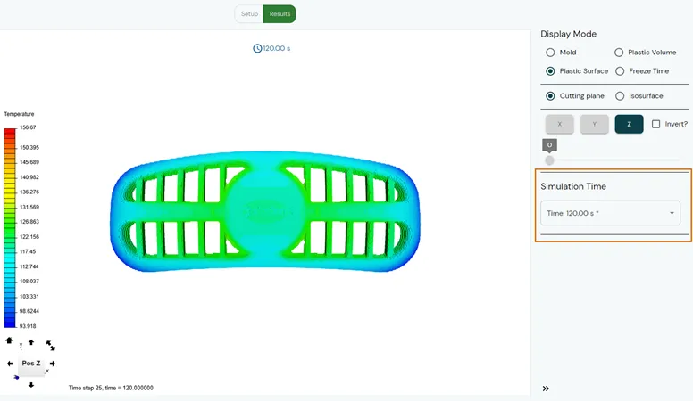
- Display temperatures inside the plastic volume using Plastic Volume or surface temperatures of the plastic part using Surface Temperature to locate areas that need more cooling and decide what type of cooling is most effective for your plastic part.
- Use Cutting plane to display the temperature distribution inside the mold and plastic part volumes.
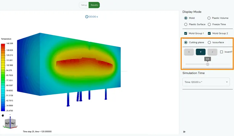
- Use Isosurface to display surfaces with same temperature value.
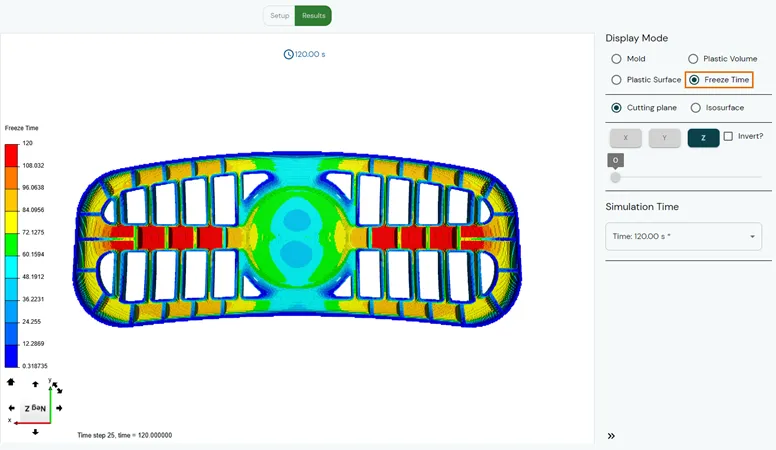
- Display the plastic local freeze time, which is time required for the plastic part surface to locally develop a frozen layer thick enough for the part to be ejected without ejector pins causing damage. SimForm also reports the overall freeze time which is the safe ejection time for all the plastic part. This is the maximum local freeze time.
- Use the Simulation Time panel to display the transient temperature results at every time step of the simulation.
The results show that the high-temperature zones and high freeze time are located inside the pockets of the grill. For efficient cooling, we must use conventional cooling channels with baffles to redirect flow near the high-temperature zones or conformal cooling channels that follow the geometry of the plastic part to reach the areas closer to the plastic part.
Conclusion
In this article, SimForm is used to run a channel planner analysis. Conducting a thermal analysis before including the cooling channels allow locating the hot spots where cooling is most needed. Based on these results provided by SimForm, you can decide where to place the cooling lines to get efficient cooling and avoid overcooling which reduces the manufacturing cost of the mold. Once you identified the best cooling circuit for your mold, you can confidently add other mechanisms without compromising the cooling process.
After running a channel planner analysis, you can use SimForm to test different cooling designs and compare the freeze time to the molder’s expected cooling time. This will help you ensure that your mold design meets the molder’s requirements. Follow the procedure described in Mold Cooling Thermal Analysis Using Basic Channels, to learn how to use SimForm to analyze molds with cooling channels.