by Sarra Zoghlami
Introduction
SimForm is a web application that enables designers to evaluate the thermal behavior of plastic injection molds earlier in the design process. With SimForm, you can run multiple thermal analyses of your design to compare cooling performance, select efficient cooling methods, and optimize the cooling process, reducing injection molding cycle time.
In this tutorial, you will explore SimForm’s capabilities using the sample models provided in the application to analyze a conventional cooling design. This hands-on experience using SimForm’s features will show you how to effectively use the application to analyze the thermal performance of different mold cooling designs.
Presenting the sample models
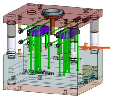
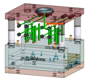
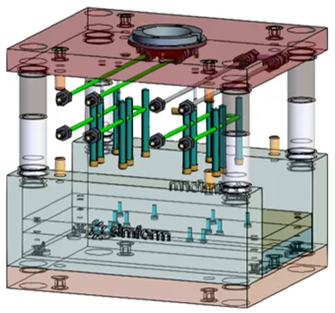
The sample models consist of mold designs, cooling channels, and plastic parts for a computer mouse shell. One model includes conventional cooling channels, while the other model incorporates more complex conformal cooling channels.
| Conventional cooling model | Conformal cooling model |
|---|---|
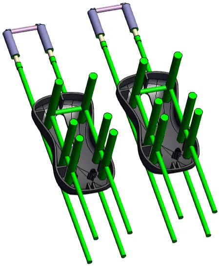 | 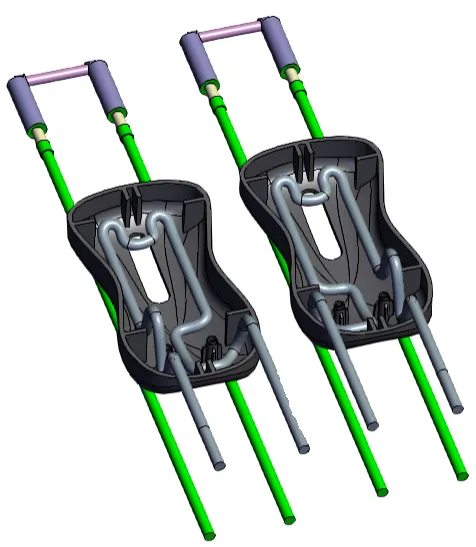 |
Creating a new project and job
In SimForm, you create a project to test different designs of the plastic part and mold for your application. A single test of the model is called a job. A project can contain multiple jobs with different variations of the part and mold to easily converge upon the optimal design. Each job allows you to evaluate a specific cooling channel design.
For this example, you will create a new project and job for the mouse shell mold design.
-
On the Projects page, click Design Project.
 The Add Design Project window opens.
When you create a new SimForm project, you redeem 10 credits from your credit balance. Each project lets you to simulate up to 10 different solves (5 solves during the free trial) without using more credits. -
In the Add Design project window, type a meaningful name that identifies your part design, for example Mouse shell.
-
Click ADD.
The Add a new job window opens. -
In the Start with a sample model panel, select one of the sample models. For this example, select CONVENTIONAL.

Defining the mold and plastic part components
You will categorize the model components to let SimForm identify the mold components and plastic part.
The mold group panels let you categorize the various parts of your mold based on their material properties. If your mold includes inserts made of a different metal material than the mold, you can use a mold group panel to categorize the core, cavity, and other components made of the same metal material. Then, use an other mold group panel to categorize the inserts with a different material. This ensures that the results of the thermal analysis are based on the specific material properties of each component.
By default, the setup page contains one mold group. You can add additional mold groups to categorize and analyze various material properties within your mold design.
The mold design used in this example does not contain inserts made of different metal materials. Therefore, you can use the Mold Group 1 panel to categorize the core and add an additional mold group panel to categorize the cavity. This allows you to display the temperature of the core and cavity separately on the result page.
To categorize the mold components and the plastic part:
- Click Mold Group to add an additional mold group.

- Graphically select the first mold group. For example, the mold cavity.
-
In the Mold Group 1 panel, click the + sign to define the selected body as a mold component.
-
Click the visibility icon to hide the categorized components.

This allows you to verify if all your components are correctly categorized by hiding the selected ones. -
Repeat steps 1 and 2 to select the sprue bushing and add it as a part of the Mold Group 1.
-
Repeat steps 1 to 3 to select and define the core of the mold using the Mold Group 2 panel.
-
Select the ejection pins and add them as a part of the Mold Group 2.
You must categorize all components in contact with the plastic part as part of one of the mold groups to ensure accurate temperature results. Not including them in the analysis creates an additional source of cooling that distorts the temperature results and the cooling time estimation.
-
Repeat steps 1 to 3 to select and define the plastic part using the Plastic Part panel.
-
Use the same procedure to select and define the cold runner using the Runners sub-panel.
This allows SimForm to properly manage the runner when calculating the cooling time.
Defining the mold and plastic part material
You will define the mold components and plastic part materials. SimForm uses the thermal properties of these materials to compute the heat transfer between the mold and plastic part.
In SimForm, you can choose the material from a list of widely used materials for plastic injection molds and for plastic parts or define a new material that helps you meet the specific needs of any plastic molding project. For more information, see Creating Custom Materials in SimForm.
To define the mold and plastic part materials:
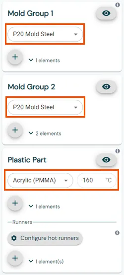
- Expand the Select Material list in the corresponding panel and select, for example, P20 Mold steel for the two mold groups and Acrylic for the plastic part.
When you select the plastic part material, SimForm sets the injection temperature for the plastic based on manufacturer recommendations. You can modify the injection temperatures of the plastic part if necessary.
Defining the cooling channels
You will first categorize all the channels, and then identify inlets and outlets for each categorized channel.
To identify the cooling channels in your model:
- Press and hold the Ctrl key, and select all the cooling channels in the model.
- In the Channels panel, click the + sign to define all the selected bodies as channels.
In this example, 4 channels are selected.

In the SimForm app, the Detect Baffles Automatically option is enabled by default, which allows the software to automatically detect the baffles.
For models with complex geometries, you can also manually define baffles. For more information, see Defining Baffles in SimForm.
SimForm uses a color-coded system to help you visualize and verify the setup of your model. Once the cooling channels are categorized, the detected baffles are highlighted in turquoise.
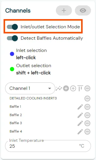
- Enable the Inlet/outlet Selection Mode to define the inlets and outlets for the channels.
-
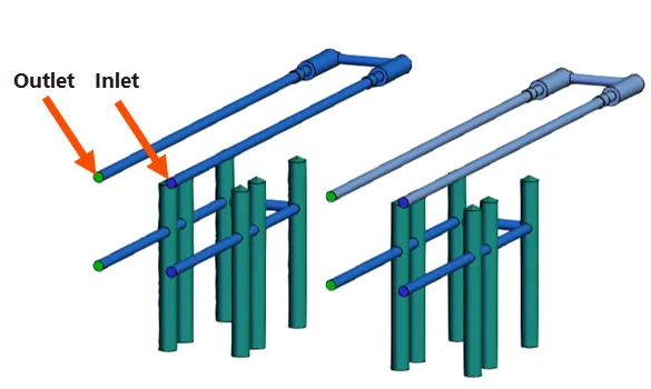
For each cooling channel, click the inlet surface to designate it as an inlet.
-
To define the outlet of the channel, press and hold the Shift key while clicking the corresponding surface.
SimForm allows using channels with one inlet and multiple outlets. The surface defined as the inlet changes to blue, while the outlet surface changes to green. Channels with defined inlets and outlets are displayed in blue.
- Keep the default Inlet Temperature value of 25° C.
This sets the cooling liquid inlet temperature to 25°C.
Solving the model
After categorizing the model components and defining materials and initial temperatures, the model is ready to be solved.
- Click Submit Job to solve it.

Notes:
- You can cick Cancel to terminate a summitted job before its status changes to In Progress.

- If the model setup is incomplete, the Submit Job button is unavailable. You can hover over the Submit Job button to display a list of missing items required to complete your model setup. Example:
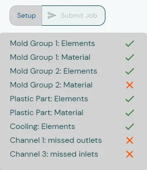
In this example, the material for Mold Group 2, the outlet for Channel 1, and the inlet for Channel 3 are not defined. You must define missing items before proceeding to solve the model.
Analyzing the results
You will open the results page and analyze the results.
-
When the solve finishes, click Results to open the results page.
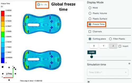
In the Display Mode panel, the Freeze Time is displayed.
The Freeze Time, or safe ejection time, is the duration for the plastic part to develop a thick enough solidified layer, enabling safe ejection while maintaining its integrity. SimForm reports overall and local freeze times, indicating the time for the plastic surface to freeze locally for safe ejection. -
Rotate the model to explore the local freeze time results in the plastic part.
- Select the Channels check box to display the cooling channels.
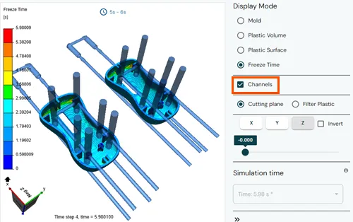
This lets you understand the impact of the channels’ placement on the results.
-
In the Display Mode panel, select Plastic Surface or Plastic Volume to display the temperature distribution either on the surface or the volume of the plastic part and inspect the temperature distribution in the plastic part.
-
Click anywhere in the plastic part to display its local result.
-
Click the scale bar in the graphics window to open the Legend settings window.
-
Type a maximum and minimum value to adjust the result scale.
-
Click Save to save the changes.
-
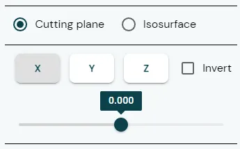
Select the cutting plane direction. For example, the X direction.
-
Move the slider to change the cutting plane position.
This allows you to display the temperatures inside the plastic part and locate the hot spots. -
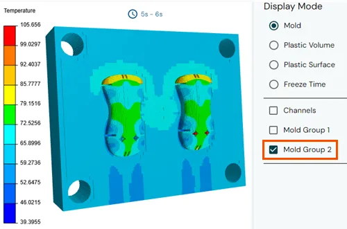
Select Mold to display the temperature distribution inside the mold volume.
-
Clear the Channels and one of the mold groups check boxes to show the temperature results on one of the mold groups and rotate your model to see the temperature inside the mold cavity.
- Select Plastic Volume and Isosurface, then move the slider to select a desired temperature to display. For example, 95°C.
The application displays areas of the plastic part where the temperature is higher than the specified temperature.
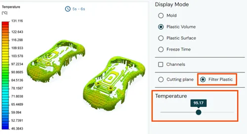
This lets you identify areas of the plastic part that are within the safe ejection temperature range, those that are still in a liquid state, or those that exceed the melting point of the plastic material.
- From the Simulation Time panel, expand the time step list and select a specific time step at which you want to display the thermal result.
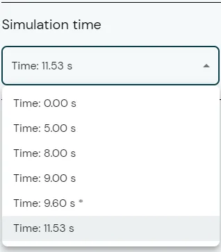
This helps you analyze the thermal performance of your mold and plastic parts during various phases of the cooling cycle.
You have completed this tutorial.
Conclusion
In this tutorial, you learned how to set up, solve, and analyze the thermal performance of the sample model using SimForm. Leveraging SimForm’s features effectively allows you to optimize mold cooling designs, make informed choices, and improve efficiency. Incorporate SimForm into your design workflow to optimize your mold cooling designs and enhance the overall results of plastic injection molding.