by Sarra Zoghlami
For mold designers who would like to use SimForm to run a thermal analysis of their mold designs with cooling channels.
Introduction
This article is a step-by-step guide to using SimForm to run a thermal analysis of a mold containing cooling channels. This workflow can be used to run thermal simulations using conventional or conformal mold cooling. You can use the analysis results to make smart decisions on how to place the channels and evaluate if the cooling approach that you are using is efficient for your design.
The model in the following example uses conventional cooling in straight cooling channels, which are usually drilled directly into the mold. These channels are in the center of the mold core and cavity, and do not depend on the plastic part shape.
You can use SimForm to:
- Test the thermal performance of your cooling channels.
- Estimate the safe ejection time.
- Analyze the effect of the position, depth, and pitch of the cooling channels on the cooling time.
- Evaluate the efficiency of conventional cooling for your design.
Content
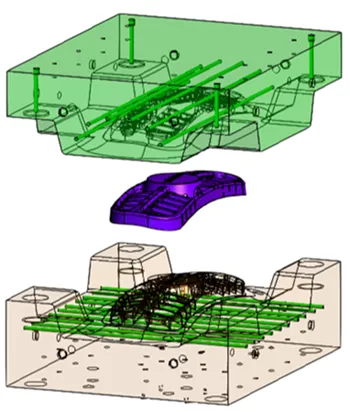
Model
The model is an All-Terrain Vehicle (ATV) grill mold that contains a plastic part, core, cavity, and parallel straight cooling channels drilled through the core and cavity.
Define a new job
In SimForm, you use a project to test different designs of the plastic part and mold for your application. To create a new project, follow the procedure described in Channel Planner Thermal Analysis to define a new project, create a new job for the conventional cooling analysis, and categorize and select the materials for the mold and plastic part components.
If you have already done the channel planner analysis:
-
Go to the project you created for that analysis and click the + sign next to Jobs to add a new job.
-
In the Add a new job dialog box, type the job name, for example basic cooling.
You can choose to keep the same CAD file as the previous job or upload a new CAD file. For this example, you will upload a new CAD file since the previous one did not have the channels. -
Click the delete icon to delete the pervious job CAD file
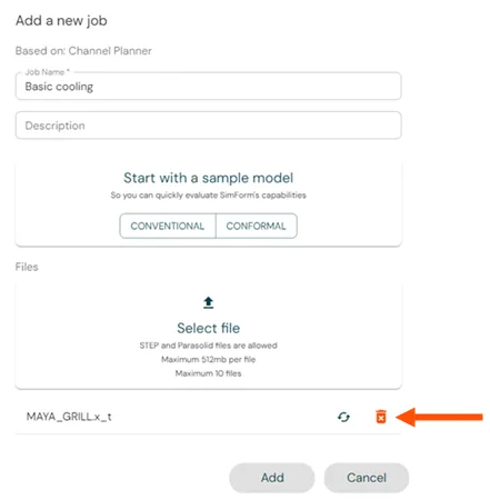
- Click Select file, select the CAD files to upload your mold design, and click ADD.
When you upload a CAD file with the same model tree as a previous job, SimForm keeps the categorization, the material definition, and the initial temperature of components with the same name as in the previous job. In this case, you can proceed directly to the Categorize and define the cooling channels section.
If the model tree of the CAD file is different than in the previous job, follow the procedure described in the Channel Planner Thermal Analysis page to categorize and define the materials for the mold and plastic part components before proceeding.
Categorize and define the cooling channels
You will first categorize all the channels, and then identify the components, inlet, and outlet for each categorized channel.
To define the cooling channels in your model, simply follow these steps:
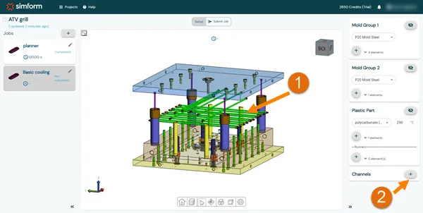
- While pressing the Ctrl key, graphically select all the cooling channels present in your model. If a cooling channel consists of multiple bodies, you must select one body within the channel initially, and add the remaining bodies later.
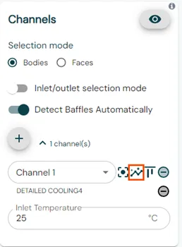
- In the Channels panel, click the + sign to define all the selected bodies as channels.
- For cooling channels that consist of multiple bodies, click Add Body to identify the remaining components of the channel.
- In the Channels panel, enable the Inlet/outlet Selection Mode.
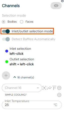
- For each cooling channel, click on the inlet surface to designate it as an inlet.
- To define the outlet of the channel, press the Shift key while clicking on the corresponding surface.
SimForm allows using channels with one inlet and multiple outlets.
The surface defined as the inlet changes to purple, while the outlet surface changes to green. Channels with defined inlets and outlets are displayed in blue.
The channel components, its inlet and outlet are listed under the channels list.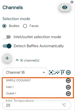
SimForm automatically sets a flow rate that ensures a turbulent flow in the cooling channels. It uses the channel diameter to compute the fluid velocity assuming that the Reynold’s number of the flow is equal to 10 000. The default cooling liquid temperature is 25ºC. You can modify it if necessary.
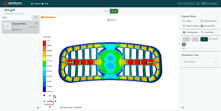
Solve the model and analyze the results
After you prepared your model by categorizing the model components and defining materials and initial temperatures, you can perform a solve by clicking Submit job. When the job finished, you can click Results to open the results page.
As described in the in the Channel Planner Thermal Analysis page, on the results page, you can display the temperature distribution in the mold and the plastic part volume and surface which lets you evaluate the efficiency of the cooling circuit design and identify the areas where more cooling is needed. You can also analyze the safe ejection time and compare it to the expected cooling time to verify if your mold design meets the requirements of the molder.
In the following table, we compare the results with and without the cooling channels to evaluate the impact of the basic cooling channels on the temperature distribution of the mold and the molding cycle time.
| Channel planner results | Basic cooling results | |
|---|---|---|
Overall freeze time | 120 s | 82 s |
Local freeze time | 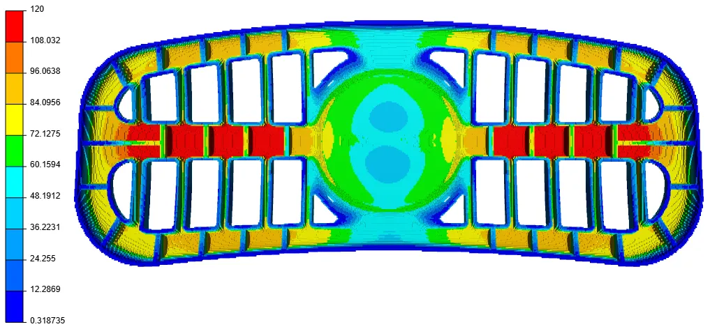 | 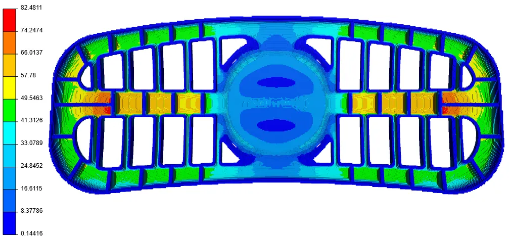 |
Plastic part temperature | 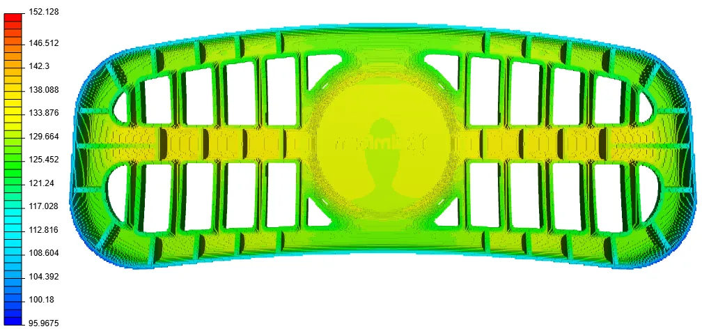 | 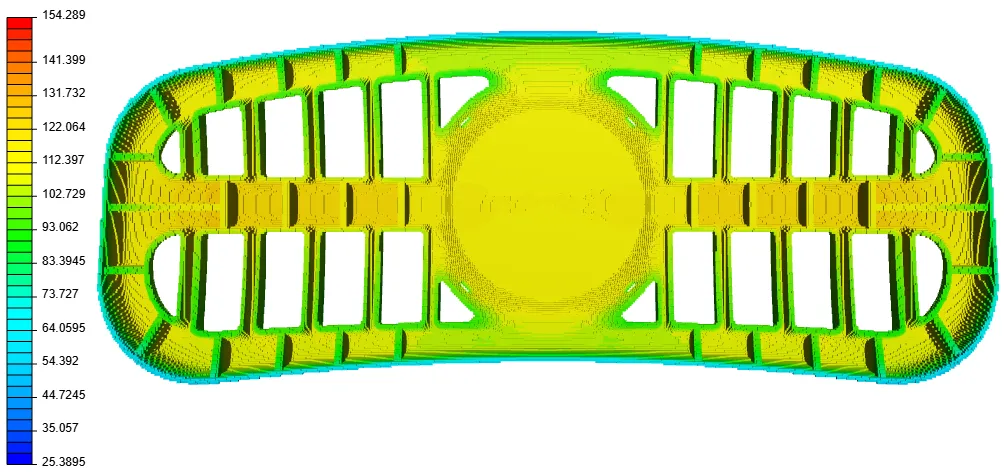 |
| Mold temperature distribution | 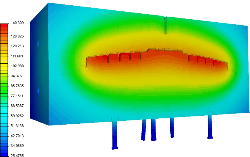 | 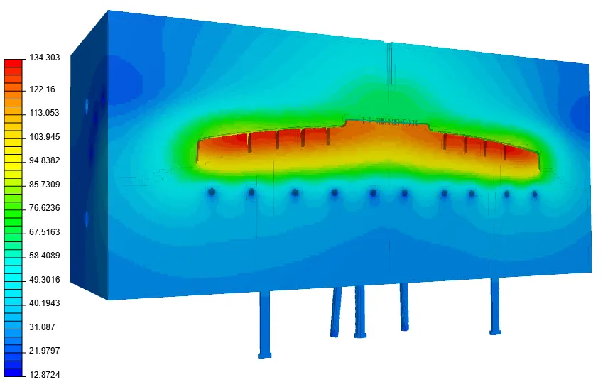 |
The temperature distribution shows that basic cooling channels significantly reduce the temperature in the mold core and cavity. However, the temperature and local freeze time are still high inside the pockets of the plastic part. Thus, it is not needed to add cooling inside the mold components, and it would be more efficient to include baffles to divert the flow to the high temperature regions or add conformal channels that follow the plastic part geometry to remove more heat closer to the grill.
Conclusion
In this article, SimForm was used to analyze a mold with basic cooling channels. The results of this analysis let you evaluate the performance of a simple cooling design and identify areas that need more cooling so that you can add baffles or complex cooling circuits only in the required locations. Performing basic cooling channel analysis reduces the time required to design cooling channels in areas where basic cooling is sufficient to cool and limits the number of baffles that need to be added to the cooling circuit. This simplifies and reduces the cost of mold manufacturing. Based on the basic cooling analysis results, you can improve the cooling circuit by using SimForm to run several analyses on different variations of the part and mold to easily converge upon the optimal design. In Using SimForm to Evaluate Different Cooling Channel Designs, SimForm is used to compare two mold designs. The first one uses conventional cooling channels with baffles to divert the flow to the high temperature regions and the second one uses conformal cooling channels that follow the plastic part geometry. Comparing the results helps to evaluate the effectiveness of the two mold designs in improving cooling and reducing the safe ejection time.